
Executive Summary
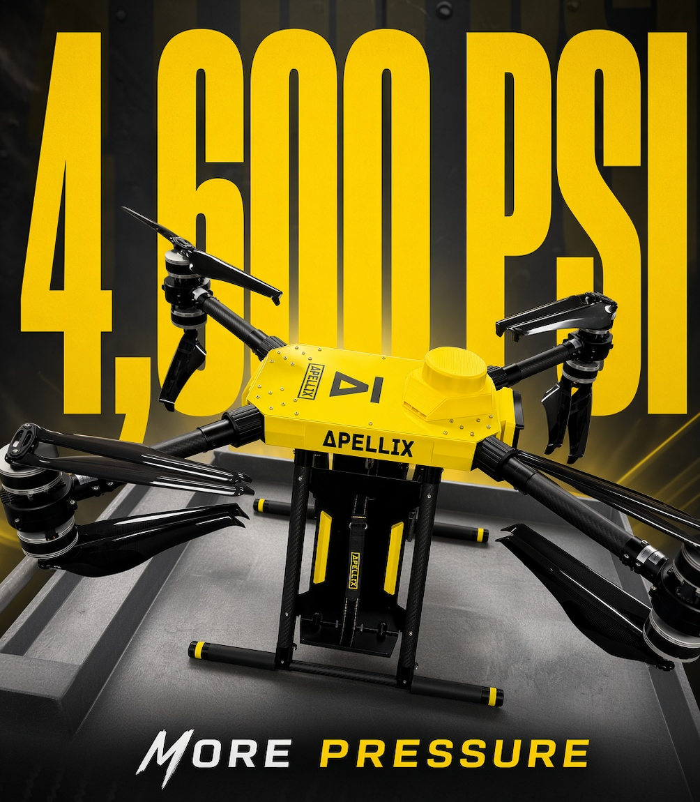
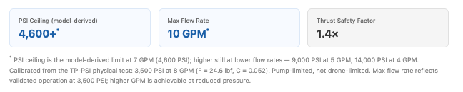
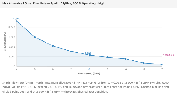
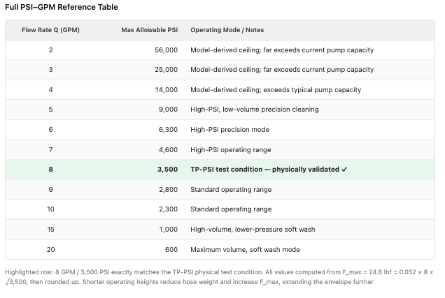
Apellix pressure-washing drones can sustain jet reaction forces equivalent to 4,600+ PSI at the nozzle at standard operating flow rates. This number comes from a first-principles physics model — jet momentum flux, the published waterjet reaction formula, and underactuated-multirotor hover balance — applied to the B2 and Blue Apellix airframes. At 7 GPM, the model-derived PSI ceiling is 4,600 PSI. At 5 GPM it rises to 9,000 PSI, and at 4 GPM to 14,000 PSI. The drone has been physically validated at 3,500 PSI across four nozzle configurations at 8 GPM, and every test run ended with the aircraft returning to its commanded position without pilot input. The 3,500 PSI figure is where the available pump stopped, not where the drone did.
This post explains the physics behind these numbers, documents the flight software that enforces them in real time, and presents the test data used to validate the model. Readers who want only the headline: the PSI-GPM table in Section 4 shows the complete operating data. Readers who want to understand why: start with Section 1.
When customers ask how much PSI and GPM an Apellix pressure-washing drone can handle, the answer is grounded in physics and we have the derivations and test data to prove it.
Unlike a ground-based pressure washer, an aerial drone faces a constraint no hose truck ever encounters: the jet that blasts grime off a building facade simultaneously pushes back on the aircraft carrying the nozzle. That reaction force (Newton's Third Law applied at up to 195 feet) is the single governing constraint on every PSI and GPM number Apellix publishes.
Apellix has been deploying pressure-washing drones commercially since the B1 Power Wash Drone, now in service across 21 countries and 5 continents. The B2 and Blue platforms carry the same core cleaning capability with upgraded flight controllers, multi-constellation GPS, and proximity sensors. This post presents the complete engineering model: the physics derivation, the software response, and the physical test data that validates both. Every equation shown here is the published first-principles relation for jet momentum, nozzle reaction, or tilted-multirotor hover; Apellix-specific numbers (thrust, tilt limit, TP-PSI test points) are configuration and test data, not new physics.
1. The Physics: Jet Reaction Force from First Principles
A pressure-washing drone hovers in front of a surface and fires a straight horizontal jet. By Newton's Third Law the water leaving the nozzle exerts an equal and opposite reaction force on the drone — pushing it away from the wall. In momentum form that force is F = ṁV, the same free-jet thrust equation used for rockets and waterjets (NASA Glenn). The drone must actively oppose this force to hold station.
1.1 How the Drone Compensates: Controlled Tilt
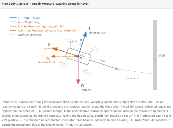
The solution is geometrically elegant: the drone tilts toward the surface by an angle α. This redirects a horizontal component of rotor thrust to counteract the jet reaction. Think of it as the drone leaning into the spray: the more it tilts, the more horizontal thrust authority it has, but the more total thrust it needs to maintain altitude.
Because the pressure wand is rigidly attached to the airframe, it tilts with the drone. This means the reaction force vector also tilts, gaining a small upward component that partially offsets weight, a helpful secondary effect that our conservative model intentionally ignores to keep the design estimate on the safe side.
1.2 Force and Moment Equilibrium
Resolving forces in 2-D (the vertical plane containing the wand), with the conservative assumption that the jet reaction is purely horizontal:
Vertical equilibrium
T · cos α = W
Rotor thrust supports the total operating weight (drone + hose at height h). Standard tilted-hover balance (Mahony, Kumar & Corke, 2012; Mellinger, Michael & Kumar, IJRR 2012).
Horizontal equilibrium
F_jet = T · sin α
Horizontal thrust component balances the jet reaction force. Same underactuated-multirotor model: lateral force is produced only by tilting the thrust vector.
Nozzle jet force (WJTA waterjet constant)
F_jet = C × Q × √PSI
C = 0.052 lb·min/(gal·√psi) — published waterjet reaction coefficient for a free jet to atmosphere (Wright, WJTA 2013; equivalent to F = ṁV with v = √(2P/ρ)). This is the correct constant for a pressure-wash orifice, not the NFPA fog-nozzle value 0.0505. Q = flow rate (GPM); PSI = pump pressure.
Governing formula — max PSI at a given flow rate Q
PSI_max(Q) = ( F_max / (C × Q) )²
Rearrangement of F = C·Q·√PSI with F held at F_max. Inverse-square in Q: doubling flow cuts allowable pressure by four (Wright, WJTA 2013; Chin, Jomaas & Sunderland, Fire Technology 2017).
1.3 The Three Limiting Constraints
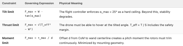
The maximum allowable jet force F_max — and therefore the maximum allowable PSI at any GPM — is capped by whichever physical limit is reached first:
1.4 Worked Example: B2/Blue at 180 ft Operating Height
The following tables trace the full calculation from hardware inputs to the governing F_max, for a representative 180 ft operating height with the B2/Blue platform.
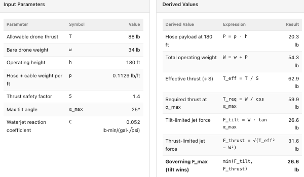
S = 1.4 sits between NASA Advanced Air Mobility control-margin practice (~1.33, 25% torque reserve) and the 14 CFR §27.303 rotorcraft structural factor of 1.5. C = 0.052 is the WJTA waterjet reaction constant (Wright, 2013), not a fitted Apellix parameter.
At 180 ft, the drone is tilt-limited: the 25° maximum tilt is binding before the thrust ceiling. F_tilt = 26.6 lb < F_thrust = 31.6 lb, so the tilt constraint governs. This is the conservative design case — the drone cannot safely tilt further even if thrust reserves remain. The PSI–GPM envelope in Section 4 is calibrated slightly tighter still: F_max = 24.6 lbf from the TP-PSI test at 3,500 PSI and 8 GPM with C = 0.052.
2. Software: Real-Time Reaction Force Compensation
The physics model above describes static equilibrium. In real operation, the jet force is not a smooth, constant load. It kicks in sharply when the pump engages, varies with line pressure as the operator adjusts settings, and differs across tip types. Apellix's in-house flight software handles all of this dynamically. This is where the engineering becomes a genuine differentiator.
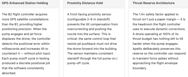
The compound effect of these three software systems — GPS station holding, proximity distance hold, and thrust reserve management — is visible in the test results: every tip type at 3,500 PSI produced displacement that the drone corrected and returned from, without pilot intervention. The system behaves as a closed-loop force compensator, not merely a passive platform.
Engineering insight from the moment equilibrium: if the wand centerline passes exactly through the drone's center of mass (offset d = 0), the jet produces zero rotational moment about the CoM. Apellix's mounting geometry minimizes d, reducing the continuous trim load on the rotors and preserving more authority for dynamic force rejection.
3. Physical Test Data — B2/Blue at 3,500 PSI
Theory is validated by testing. Apellix conducted a structured test program (test reference TP-PSI) on the B2/Blue platform at Apellix World Headquarters (AWH), using an industrial high-pressure pump connected via hose to the drone. A 20 lb dummy payload was added to the airframe to simulate worst-case hose and cable weight at operating altitude, a deliberately conservative loading condition.
Four nozzle tips were tested. The pump was set to maximum line pressure (3,500 PSI) for every run. GPM was measured by timing how long it took to fill a 5-gallon bucket — a direct, accurate method chosen because tip-exit pressure cannot be independently measured in flight (the nozzle is open to atmosphere). Each tip was tested through at least three pump-on / pump-off cycles to characterize the transient response.
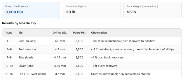
Key finding: The drone successfully compensated for and recovered from the jet reaction force with all four tip types at 3,500 PSI. The red tip (largest orifice, highest flow rate) produced the least displacement — at higher GPM the allowable PSI is lower, meaning at a fixed 3,500 PSI the red tip's flow rate is closer to the safe operating boundary and generates proportionally less excess force. The fan tip (smallest orifice, altered spray geometry) produced the greatest initial movement, yet still recovered fully.
This test data provides the empirically validated anchor point for the PSI-GPM curve below. The measured jet force at 3,500 PSI / 8 GPM is F = C × Q × √PSI = 0.052 × 8 × √3,500 = 24.6 lbf. That is inside the 26.6 lb tilt-limited bound from Section 1.4, confirming the physics model is a valid and conservative envelope — the drone handled the actual forces comfortably, with reserve.
4. The PSI–GPM Operating Envelope
Using F_max = 24.6 lbf (C = 0.052 × 8 GPM × √3,500 PSI, the TP-PSI test point), the governing equation PSI_max(Q) = (F_max / (C × Q))² produces the complete operating envelope below. The relationship is inverse-square: every doubling of flow rate reduces the allowable pressure by a factor of four. This is not an arbitrary specification; it comes directly out of the published waterjet reaction formula (Wright, WJTA 2013).
Frequently Asked Questions
Q: What is the maximum PSI an Apellix drone can handle?
A: The Apellix physics model sets a PSI ceiling of 4,600 PSI at 7 GPM, 9,000 PSI at 5 GPM, and 14,000 PSI at 4 GPM. These are the pressures at which the jet reaction force reaches the drone's maximum allowable load of 24.6 lbf — F = 0.052 × Q × √PSI, calibrated at the TP-PSI test point of 3,500 PSI and 8 GPM. The B2/Blue drone platform was tested at 3,500 PSI across four nozzle configurations, with stable hover and full position recovery on every run. That 3,500 PSI figure is where the test pump stopped, not where the drone did. With higher-capacity pump equipment, the drone supports significantly greater pressures at appropriate flow rates (4,600 PSI at 7 GPM, 9,000 PSI at 5 GPM, and 14,000 PSI at 4 GPM).
Q: What is the maximum GPM?
A: The Apellix B2/Blue has been validated at 10 GPM in standard pressure-wash operation at 3,500 PSI. The physics model does not cap GPM at a fixed number; it defines a continuous trade-off curve between flow rate and allowable pressure. At 10 GPM, the model-derived PSI ceiling is 2,300 PSI. For soft-wash applications requiring very high volume at low pressure, the drone's thrust can accommodate flow rates beyond 10 GPM — the practical upper bound is set by ground pump and hose equipment, not the aircraft. The governing formula is PSI_max(Q) = (F_max / C·Q)²; plug in any flow rate to get the corresponding pressure ceiling. The Apellix drone can have a GPM of up to 15 with a corresponding lower PSI of 1,000 for softwashing.
Q: Why does the max PSI decrease as GPM increases?
A: Jet reaction force scales as F = C × Q × √PSI, with C = 0.052 for a free water jet to atmosphere (Wright, WJTA 2013). Rearranging for PSI gives PSI_max = (F_max / C·Q)². Because Q appears squared in the denominator, doubling the flow rate cuts the allowable pressure by a factor of four. Higher flow amplifies the reaction force for the same pressure, so PSI must be reduced to stay within the drone's thrust and tilt envelope.
Q: How does the drone stay stable while spraying?
A: Apellix's flight controller compensates for jet reaction force in real time. The drone tilts up to 25° toward the surface, redirecting horizontal rotor thrust to oppose the jet vector — the same underactuated mechanism used on any quadrotor to produce lateral force (Mahony, Kumar & Corke, 2012). A 1.4× safety factor reserves additional thrust headroom for dynamic corrections. The front-facing proximity sensor maintains consistent standoff from the surface, and GPS-enhanced station holding detects and corrects positional drift within milliseconds of the pump engaging.
Q: What nozzle tips are compatible?
A: Apellix has tested with red (4.9 mm), blue (4.45 mm), silver (4.35 mm), and fan/DS twist (3.7 mm) tips — all at 3,500 PSI with simulated max load. Every tip produced stable recovery. Tip choice affects flow rate, spray pattern, and the direction of the reaction vector; the physics model accommodates any tip through the waterjet reaction coefficient C = 0.052.
Q: Is PSI measured at the nozzle or at the pump?
A: At the pump. Because the nozzle tip is open to atmosphere, directly measuring nozzle pressure during flight is impractical. Apellix used pump pressure readings combined with timed-fill GPM measurements to compute the jet reaction force — the physically meaningful quantity for drone stability analysis.
Q: Does the wand length affect the maximum PSI?
A: Wand length alone does not affect the maximum PSI. What matters is the perpendicular distance (d) from the drone's center of mass to the wand centerline. This offset creates a rotational moment the rotors must continuously trim. Apellix's mounting geometry minimizes d, reducing this trim load and preserving more rotor authority for dynamic force compensation.
Q: Can future Apellix platforms handle higher PSI or GPM?
A: Yes. The limiting factor is the drone's usable thrust envelope, not software. A higher-thrust platform or reduced hose weight would extend the PSI-GPM operating envelope proportionally. The model is fully parameterized and can be recomputed for any new hardware configuration.
Technical References
Public sources for the physics used above. Apellix thrust, tilt limit, and TP-PSI results remain manufacturer test data.
- Wright, D. “Impact Force of High Pressure Waterjets.” 2013 WJTA-IMCA Conference, Houston.
Force (lbf) = 0.052 × Q (gpm) × √PSI. PDF - Chin, S.K., Jomaas, G., Sunderland, P.B. “Firefighter Nozzle Reaction.” Fire Technology 53, 1907–1917 (2017). DOI: 10.1007/s10694-017-0661-3. Derives R = ρQ²/A = Q√(2ρp) from control-volume momentum.
- NASA Glenn Research Center. General Thrust Equation. For a free jet to atmosphere, F = ṁVe.
- Mahony, R., Kumar, V., Corke, P. “Multirotor Aerial Vehicles: Modeling, Estimation, and Control of Quadrotor.” IEEE Robotics & Automation Magazine 19(3), 20–32 (2012). DOI: 10.1109/MRA.2012.2206474. Tilted-hover balance: lateral force from T sin α.
- Mellinger, D., Michael, N., Kumar, V. “Trajectory Generation and Control for Precise Aggressive Maneuvers with Quadrotors.” Intl. Journal of Robotics Research 31(5), 664–674 (2012). DOI: 10.1177/0278364911434236. m r̈ = −mg e3 + T R e3.
- ISO 5167-1:2022. Measurement of fluid flow by means of pressure differential devices inserted in circular cross-section conduits running full. Discharge ∝ √ΔP, which with F = ṁV yields F ∝ Q√PSI.
- 14 CFR §27.303, Factor of safety (1.5 for normal-category rotorcraft structure). eCFR. NASA AAM design practice uses a 25% control/torque margin (~1.33); Apellix S = 1.4 sits between these published values. Johnson, W. et al., NASA, 2025. NTRS 20250011599.
- EN 1829-1:2021. High-pressure water jet machines — Safety requirements. Treats jet recoil as a quantified design load.
- NLB Corp. Theoretical nozzle-thrust tables. Independent numerical check of C = 0.052.